Table of Contents
Intro
Alright, we have the chassis, the disks, the board, and all the other stuff nicely put together. It is time to put some life into the silicon and the wires and make the disks work. The goal is to have a fully functional and glitch-free Linux system that can spin the disks up and down.
A year ago or so, I wrote a post about installing Linux on the NanoPi M4 board. Most of it is still applicable, except for U-Boot and some of the Linux kernel configuration. U-Boot has progressed nicely, and, as of version 2021.1, no binary crapware is necessary to run the board stably. The memory timing (DRAM needs to be refreshed to work) issues have been fixed. Let's start from the beginning, though.
Fun with Bootloaders
There are about half a quadrillion ways in which you can integrate an ARM processing core into your system. It means that the boot-up process needs to be flexible and, more often than not, ends up being a pretty weird beast. Perhaps the situation is similar on PCs, but I don't know enough about it yet to judge. I will play more with a PC boot-up process as one of my following toy projects.
Sometimes things are easy. You always have to start with some boot-up code in ROM that does some very basic device initialization, looks for a bootloader (i.e., on an SD card), loads that bootloader to SRAM, and jumps to executing it. The bootloader is loaded to SRAM because dynamically initializing DRAM timings using SPD or even statically is too much to do for the ROM bootloader (a.k.a. the Primary Program Loader). The code required to do that is usually too large. The bootloader then initializes the DRAM and whatever else is needed, loads the OS kernel to DRAM, and jumps to it.
The bootloader code itself may be pretty big, though, with all the filesystem, USB, network, and other drivers. It may not fit into SRAM, which is expensive and usually very limited. In that case, the bootloader could be split into two parts: the Secondary Program Loader (SPL) and the bootloader proper. The ROM code then loads the SPL to SRAM, the SPL sets up the DRAM, loads the bootloader proper to DRAM, and starts executing it.
Still, the amount of available SRAM may be so low (e.g., 4K) that having a big enough SPL to dynamically configure DRAM using SPD is impossible. There are usually other things we could still do. For example, in many such platforms, an L2 CPU cache could be locked and used as SRAM. To support those cases, people came up with Tertiary Program Loaders. The ROM code starts with loading the SPL to the small SRAM. The SPL locks the L2 cache to use it as a larger SRAM bank and loads the TPL there. The TPL's role is the same as the SPL's was in the previous paragraph.
On the Rockchip RK3399 SOC in the NanoPi M4 things are even more peculiar. The details are described here and here in section 1.2. It boils down to the following:
- The ROM code looks for the bootloader image on various devices.
- The ROM code loads the DRAM initializer part of the bootloader to SRAM and runs it. The DRAM initializer's role is typically played either by U-Boot's TPL or by Rockchip's proprietary code.
- When the DRAM initializer is done, it passes the control back to the ROM code.
- The ROM code loads small boot code to DRAM and runs it. This role is played either by the U-Boot's SPL or by the Rockchip's proprietary mini loader.
- The boot code loads the ARM Trusted Firmware stage BL31 (more below) at EL3 (Exception Level 3, more here) as a secure monitor.
- The trusted firmware runs U-Boot proper at EL2.
ARM Trusted Firmware
To quote ARM's documentaiton:
Arm TrustZone technology is used on billions of application processors to protect high-value code and data. Arm TrustZone technology offers an efficient, system-wide approach to security with hardware-enforced isolation built into the CPU.
That's the theory and probably even the practice. That said, I have mostly seen it used as an abstraction/mediation layer between the OS and the hardware so that the OS can have a uniform way to manage the power settings and devices and not mess up too much. I am probably quite biased because I do not care about the DRM use cases or anything similar.
The Trusted Firmware on Aarch64 divides the boot stages as follows:
- Boot Loader stage 1 (BL1) AP Trusted ROM
- Boot Loader stage 2 (BL2) Trusted Boot Firmware
- Boot Loader stage 3-1 (BL31) EL3 Runtime Software
- Boot Loader stage 3-2 (BL32) Secure-EL1 Payload (optional)
- Boot Loader stage 3-3 (BL33) Non-trusted Firmware
You can read the detailed documentation for all these here. On Rockchip, the BL1 and BL2 stages are supplied by U-Boot's TPL/SPL duo or the Rockchip's proprietary equivalents. BL31 is implemented by ARM Trusted Firmware. I omit BL32, but you could use something like OP-TEE, and the Rockchip's bootloader likely includes something of their own making. I never needed anything like this, so I don't know much about it. BL33 is U-Boot proper.
Going back to BL31, the documentation says that it redoes some of the configuration done by the previous stages of the boot process, installs its own exception handlers, and is responsible for providing a bunch of services to the operating system. One of them is Power State Coordination Interface (PSCI) that switches the CPU cores on and off, performs reboots, etc. On platforms like Xilinx's ZynqMP, I have seen it managing access to clock sources.
The Bootloader Build Instructions
Okay, all the theory is nice, but we need to get the board to boot. The first step is to build the BL31 stage of the ARM Trusted Firmware.
git clone https://github.com/ARM-software/arm-trusted-firmware.git
cd arm-trusted-firmware
git checkout v2.4
make CROSS_COMPILE=aarch64-linux-gnu- PLAT=rk3399 bl31
Then, you need to build U-Boot and make the SD card bootable:
git clone https://gitlab.denx.de/u-boot/u-boot.git
cd u-boot
git checkout v2021.01
export BL31=/path/to/arm-trusted-firmware/to/bl31.elf
make nanopi-m4-rk3399_defconfig
make
sudo dd if=u-boot-rockchip.bin of=/dev/sda seek=64
sync
Installing Linux
We are now free of the Rochkchip's BL32 stage, and the ARM's BL31 stage executes solely in SRAM. Therefore, there is no longer any inaccessible undeclared RAM allocated for the EL3-level firmware and nothing for Linux to trip over. The Linux memory patch described in the previous post is no longer necessary.
Configuration-wise, we need to add a couple of features to the kernel that are
generally not meant for ARM and thus not enabled by defconfig. These are
RAID-4/RAID-5/RAID-6 mode and Crypt target support, and you can find them in
Device Drivers -> Multiple devices driver support (RAID and LVM). We need
those for the RAID setup and the LUKS encryption. I also want my NAS device to
serve NFS; this requires some kernel support which is enabled by ticking
NFS server support for NFS version 4 in
File systems -> Network File Systems -> NFS server support. That's pretty much
it. Everything else should work as described in the other article.
Making Disks Quiet
My NAS box lives in my living room, so I want my disks absolutely quiet whenever they are not used. Seagate has their "Extended Power Conditions - PowerChoice" thingy that just works, as opposed to the WD disks that are tricky to spin down and seemingly unable to do that without manual intervention from the OS. Seagate provides a bunch of open-source tools to manage the disk settings and query the status.
git clone --recursive https://github.com/Seagate/openSeaChest.git
cd openSeaChest/Make/gcc
make release
The build process creates a bunch of executables in the openseachest_exes
directory.
The EPC functionality mentioned above supports four power-saving modes that you can set up to kick in after a certain amount of time has passed since the last activity. Here's a summary of these modes and the settings I use:
| Mode | Description | My timer |
|---|---|---|
| idle_a | Electronics in power saving mode | 100 ms |
| idle_b | Heads unloaded; spinning at full RPM | 120000 ms |
| idle_c | Heads unloaded; spinning ar reduced RPM | 300000 ms |
| standby_z | Heads unloaded; motor stopped | 900000 ms |
Here's how to set it up:
./openSeaChest_PowerControl --device /dev/sda  --EPCfeature enable
./openSeaChest_PowerControl --device /dev/sda  --idle_a 100 --idle_b 120000 --idle_c 300000 --standby_z 900000
And here's how to query it:
./openSeaChest_PowerControl --device /dev/sdc --showEPCSettings
You want to monitor the number of the load/unload cycles (aka. the number of head parks) because the heads are susceptible to wear and tear. The user's manual says that the IronWolf disks can support 600k of these cycles before a failure. Start/stop cycles (aka. spinning down and up again) is probably another metric worth tracking, but I have not seen any info on how many of those a disk can handle before failing.
You can poll these with the command below. The value that you want to look at is the last one, and the tools show it only in hex for your convenience ;)
./openSeaChest_SMART -d /dev/sdd --smartAttributes raw | grep -E "Start/Stop|Load-Unload"
Disk Power Issues
When choosing the power supply, I had foolishly assumed that the power consumption information for the disks posted on the retailer's website paints a more or less complete picture of what's needed. I then chose a power supply with a healthy margin and assumed things are going to work fine. They did for my previous setup with WD disks, so I saw no reason they would not work here. Things indeed work fine as long as you don't spin the disks down, which is a must for me. According to Seagate's user manual that you need to look pretty hard for, the disks need roughly 1.7 Amps at 12 Volts to spin up. The Phobya power supply I had initially intended to use can only deliver about half of the necessary power. I learned it the hard way by observing the Linux kernel spit out many AHCI link errors like the one posted below (in case someone wants to google it) and losing data on some of the disks. Fortunately, it never happened to more than one disk at a time. Hooray for RAID5!
[  697.033445] ata2.00: exception Emask 0x10 SAct 0x80000000 SErr 0x190002 action 0xe frozen
[  697.034246] ata2.00: irq_stat 0x80400000, PHY RDY changed
[  697.034754] ata2: SError: { RecovComm PHYRdyChg 10B8B Dispar }
[  697.035315] ata2.00: failed command: READ FPDMA QUEUED
[  697.035796] ata2.00: cmd 60/08:f8:00:89:59/01:00:6f:01:00/40 tag 31 ncq dma 135168 in
                        res 40/00:f8:00:89:59/00:00:6f:01:00/40 Emask 0x10 (ATA bus error)
[  697.037699] ata2.00: status: { DRDY }
[  697.038058] ata2: hard resetting link
The openSeaChest toolkit makes it possible to enable the feature
called Low Current Spinup. I could not find any helpful information about it,
and I did not measure how much less current the device took when the feature
enabled. It comes with three modes: disable, low, ultra. Neither low nor
ultra-low mode made the issues mentioned above go away.
openSeaChest_Configure --device /dev/sdX --lowCurrentSpinup ultra
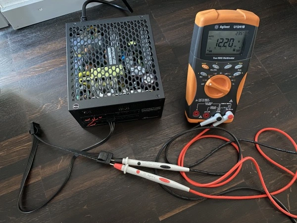
I ended up buying a 600W ATX power supply unit to power up the disks. I will also make it supply what ended up being a small cluster of ARM single-board servers that live under my TV table. Don't try that at home unless you understand what you're doing.
Conclusion
I had expected getting this far to be just going through the motions, but it proved a bit more challenging than that. I am happy, though, because it provided an excellent excuse to dig deeper into topics that interest me quite a bit and that I hate exploring in the vacuum.