Table of Contents
Intro
For some time now, I have been watching people at work and over the Internet building all sorts of cool stuff by mixing 3D-printed components of their design and electronic DYI hardware. That's something I want to learn how to do myself. Fortunately, lack of ideas for fun projects, most of which I will sadly never have the time realize, is not exactly something I can complain about. As it happens, for instance, I am in dire need of a pretty unusual storage solution for my home network that I amazingly cannot buy anywhere. Why not kill two birds with one stone then and try my hand at designing my own NAS device?
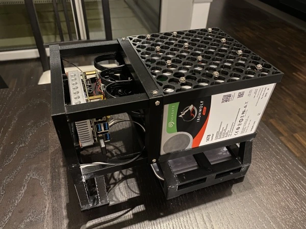
Spoiler Alert! Here's what the thing ended up looking like:
The Building Blocks
Conveniently, I already had a Prisa Mini printer and a bunch of other building blocks and tools. All I needed to do was to buy some disks. I ended up using Seagate IronWolf Pro for their open-source admin tools and because of my previous bad experiences with Western Digital and their issues with firmware upgrades, messed up head parking, problems with putting them to sleep, and the company's issues with honesty in disclosure of the SMR technology being used even in high-end devices. The problems mentioned above are described in more detail here and here.
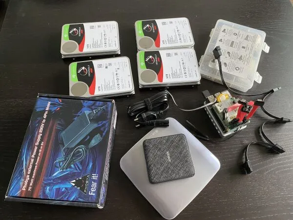
Here's the full BOM:
- A NanoPI M4
- A NanoPi M4 SATA Hat
- Four Seagate IronWolf Pro CMR disks
- An external Blu-Ray drive
- A power supply for the disks (I ended up using an ATX supply, see here)
- A power supply for the board and the Blu-Ray drive
- Four short (10-15 cm) long flexible SATA cables
- Four-way splitter SATA power supply cable
- Some jumper cables to drive out the UART debug interface
- 24 #6-32 screws and isolation rings to attach the disks
- 4 20mm long M3 screws to attach the NanoPi M4 board
- Some PLA filament to print the chasis
- Fast drying plastic glue to connect the components
Modeling
I decided that pointing and dragging things in a typical CAD program is for rookies, so I went for OpenSCAD. Using it, you can code everything up in a text editor and version control the result in git like a real pro[grammer]. There's a pretty great tutorial here that will teach you how to do all sorts of magic with it. That, the Prusa Mini instruction manual and some elementary math are all you need to know to make the figments of your imagination real. Stop here for a second and ponder how mind-blowing that is! Seriously, you type some stuff in a text editor, and there's this thing on your desk that you can buy for 346 euros that makes it such that you can touch it with your fingers. I can't stop being amazed.
The video above is the rendering of what I came up with. It's not that great because it's pretty hard to change the disks when they break, which is the whole point of having a NAS RAID array. I treat it as an upside, though, because it will be an opportunity to redesign the thing when a disk breaks down.
I loved playing with OpenSCAD, but I don't think it's suitable for large or even moderately-sized designs. It is primarily because of the limitations of the language it uses. I have briefly looked at its implementation. It's a tree-walking interpreter that builds the CGAL geometry as it goes from AST node to AST node and uses a caching mechanism to avoid recomputation of the geometry represented by the subtrees that it has seen in the past. This mechanism allows OpenSCAD to quickly re-parse and re-render the design whenever the user changes the SCAD files and saves them. It is pretty cool!
In my opinion, however, building the geometry directly from the parse tree is a design flaw that gravely handicaps composability and makes the construction of complex models with multiple custom objects very hard. Instead, a model similar to the one employed in the Java3D API would make putting modules together much more manageable. With Java3D, you can write functions that return the geometry tree nodes that can have properties such as coordinates of the joints, dimensions, etc. It, in turn, allows you to write functions taking these properties as parameters and returning transforms aligning the coordinate frames such that the joint points meet right where you want them.
This problem could be somewhat alleviated by extending the language to have maps and using functions to compute module properties. It would be pretty tedious in practice, though, because you would have to make the same call twice, first to the module itself and then to the function computing the map of the module's properties for the given input parameters. In my chassis model, I have made an attempt at a poor man's alternative to this approach using the OpenSCAD vector type. It helped somewhat, but things got pretty convoluted and confusing pretty fast.
I have a module called support with the following interface:
module support(top, num_disks, disk_dims) {}I then define a function that computes a vector of properties of the support that I call in multiple places to figure out how to fit things together in a parent module:
function support_properties(num_disks, disk_dims) = [
    [
        (num_disks - 1) * 2 * comb_size + disk_dims[0] + 2 * frame_thickness,
        disk_dims[1] + 2 * frame_thickness,
        frame_height
    ],
    frame_thickness,
    support_thickness
];
It could have been made much simpler if the module returned an object that you could pass as a child node to another module, but before you do that, you could read some of its properties to transform the coordinate frame such that things fit together in a way that you want. My next toy project will be an attempt to create such an API and a wrapper for OpenSCAD in go that will compile the geometry to the SCAD language and have OpenSCAD render it.
The language also misses other features that seem crucial. The most important of them is treating functions as first-class citizens, i.e., the ability to assign them to variables and pass them as parameters to modules. It would make things like a function grapher, one example in the tutorial I mentioned earlier, generic. Ie. You could define any function \( f: \mathbb{R}^{2}\rightarrow \mathbb{R} \) and have a module that plots it.
Initially, I wanted to add this and some other features to the OpenSCAD language. However, using a programming language like go to create the geometry tree and then having this tree compiled to the SCAD language will make this and other problems go away for free.
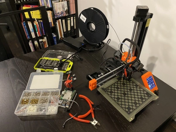
The printing and putting things together was pretty easy. The Prusa slicer takes the STL files, produces the GCODE files that the printer can handle directly. For some parts of the model, it was necessary to generate additional support, but you can read all that in the Prusa instruction manual.
Conclusion
It was my first non-trivial 3D printing project. Even though I am not completely happy with the design, it's pretty stable and solid. Most importantly, the whole process taught me a lot and gave me many ideas to improve the open-source ecosystem. I will work on them in my "copious spare time" (sarcasm ;).
The whole model is available on GitHub here.
Update 20.04.2022: I did manage to find some spare time to work on it. See this post.