Intro
OpenSCAD is awesome. Being a software engineer, the ability to code up my 3D models and keep them readably under version control pleases me immensely. I started learning OpenSCAD from this fantastic tutorial that quickly showed me the expressive power of the relatively few basic concepts provided by the system. It also made me realize some of the system's limitations.
For example, when doing the function grapher exercise, I was disappointed that I could not pass the function being plotted to the module doing the work. Instead, I had to generate an array of 3D points in a particular order so that the grapher could build the desired polyhedron out of them. It is cumbersome, and it could, in principle, be automated. It also makes the grapher module leak abstraction. You need to be aware of its internal workings to plot what you want.
The issue of leaking abstractions became more visible when I started using OpenSCAD to model the enclosure for my NAS project.
Firstly, I wanted part of the enclosure holding the disks to be parametrized by the number of disks it could contain and their size. I also wanted the part of the enclosure holding the optical drive and the ARM board to be parametrized by the size of these components. Everything worked fine until I had to figure out how to connect these parts. I could not determine the locations of bolts and screws without knowing the internals of each of the modules, and there was no obvious way for the modules to expose the necessary information to the outside world. I ended up defining a bunch of helper functions that would compute this information when supplied with the same parameters as the modules they described. It quickly became cumbersome, though, and started to look pretty ugly.
Secondly, I needed to design the components separately to 3D print them later. But I also wanted to visualize the model as a whole to see if things fit together. That ended up being impossible without knowing the dimensions of the parametrized components, the arrangement of attachments (which were a non-trivial function of the module's input parameters), and the frame of reference in which each part was designed.
The last two issues fundamentally stem from the fact that, in OpenSCAD, the abstract syntax tree of the program you're writing represents the geometry tree of the model you are designing. Significant improvements can be made if you divorce the two. For example, doing so would allow the module objects to have properties that you could use for integration without exposing how these properties were calculated internally. It would also allow for writing programs that analyze or manipulate the geometry tree in interesting ways before it is rendered. Solving the first issue is just a matter of making functions first-class citizens, which would probably be an easy change to the OpenSCAD language.
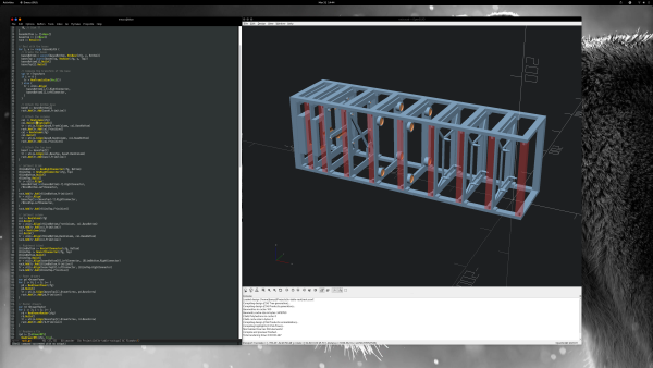
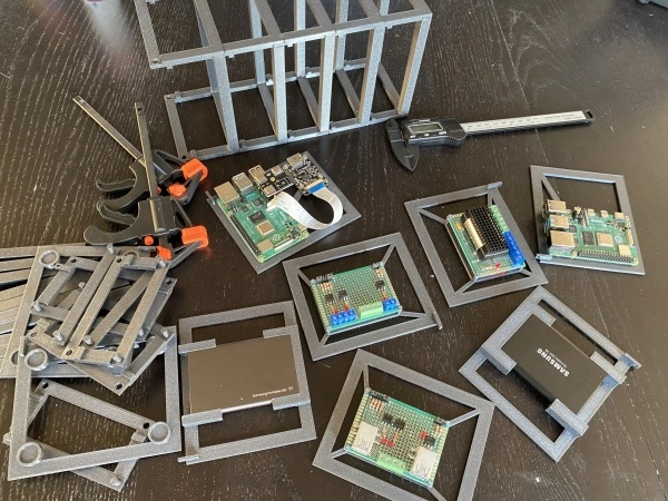
I finally managed to find enough time to make good on the threats I had made when I designed the chassis for my NAS and played with solving the issues mentioned above. I decided to use Go because it's a garbage-collected language with great tooling, and it compiles really fast. I designed a Java3D-like API that can be used to build the geometry tree of a model, which can then be compiled to OpenSCAD source and further processed by vanilla OpenSCAD. I used this system to design something of a non-trivial size that I needed - a small computer rack for all the electronic gadgets that accumulated under my TV table and evolved into a maze of wires, routers, and bare PCB boards.
I called the system GhostSCAD, and the TV table rack project is here. This article summarizes the results of this investigation.
Quick Dive
If you've managed to read this far, it is probably safe to assume that you know OpenSCAD reasonably well. I will then just cut to the chase and illustrate how to use GhostSCAD by providing a couple of examples. Since this is just a slightly new way of doing the old familiar things, it should be enough for you to get a pretty good feeling of how to use it. There's a bunch of examples here should you wish to get a complete picture.
Since Go is a general-purpose programming language, there, unfortunately, is some boilerplate that we need to manage. You need to start with creating a module and downloading GhostSCAD:
]==> mkdir model; cd model
]==> go mod init model
]==> go get github.com/ljanyst/ghostscad
You can then generate a minimal program rendering a sphere using a stub generator:
]==> mkdir test; cd test
]==> go run github.com/ljanyst/ghostscad/util/stub_generator -file-name test.go
]==> go mod tidy
You can go run this program:
]==> go run test.go
It results in an OpenSCAD source file called main.scad representing the model
defined in the program. Don't look at the generated code. It's not meant to be
human-readable.
You can also go build it and run the resulting executable to list all the
available shapes, generate the STL or OpenSCAD files for the shapes you want,
control logging levels and destinations, and so on (-help param is where you
expect it):
]==> go build
]==> ./test -list-shapes
main (default)
Here is the example program that was produced by the stub generator:
 1package main
 2
 3import (
 4 "github.com/ljanyst/ghostscad/sys"
 5 . "github.com/ljanyst/ghostscad/primitive"
 6)
 7
 8func main() {
 9 sys.SetFn(120)
10 sys.RenderOne(NewSphere(10))
11}
Everything except for the imports should look pretty familiar:
sys.SetFn(120)is equivalent to setting$fn = 120globallyNewSphere(10)builds a sphere of radius 10 just as sayingsphere(10)in OpenSCAD does. The difference is that here an object of type sphere is created that you can either manipulate or pass to the rendering function.- Calling
sys.RenderOnepasses the aforementionedSphereobject to the rendering machinery.
GhostSCAD defines all the shapes and most of the transforms supported by OpenSCAD with roughly the same convention for the parameters. Generally, the constructors take the non-optional parameters, while the setters handle the optional ones. The setters return a pointer to the object they modify so that you can chain them:
1sys.RenderOne(NewCylinder(20, 3).SetFn(24).SetRBottom(6).Highlight())
The setters are generated by a code generator based on data member annotations.
Modules that accept children in OpenSCAD generally have variadic constructors
and an Add method in GhostSCAD. It makes things look kind of lispy:
 1NewList(
 2  NewCube(Vec3{o.Cfg.BaseWidth, o.Cfg.Depth, o.Cfg.BaseHeight / 2}),
 3  NewTranslation(
 4    Vec3{0, -pinYOffset, leftConnectorZBase},
 5    NewTranslation(
 6      Vec3{0, 0, leftConnectorZOffset},
 7      o.LeftConnector),
 8    NewTranslation(
 9      Vec3{0, 0, columnZOffset},
10      o.FrontColumn)))
Each of these basic shapes and transforms implements the Primitive interface.
 1type Primitive interface {
 2  SetParent(Primitive)
 3  Parent() Primitive
 4  Disable() Primitive
 5  Highlight() Primitive
 6  ShowOnly() Primitive
 7  Transparent() Primitive
 8  Prefix() string
 9  Render(w *bufio.Writer)
10}
Parent tracking is essential for some of the tree operations discussed below.
Disable, Highlight, ShowOnly, and Transparent implement the OpenSCAD
modifier characters. Prefix returns the active modifier character, if any.
Render writes out the OpenSCAD code corresponding to the node. Some nodes
don't render any active code but serve purposes in tree manipulation. The list
of implemented primitive nodes is here.
The definition of complex shapes is somewhat more involved. By convention, a
complex shape should have a Build method constructing the geometry tree from
the primitives and storing the root in the data member called Primitive. For
instance, Polyline3d is defined by a bunch of 3d points, has a specific
thickness and a resolution of rounded connections of the segments:
1type Polyline3d struct {
2  Primitive Primitive
3  Points    []Vec3
4  Thickness float64
5  Fn        uint16 "optional"
6}
It is constructed in the following way:
 1func (o *Polyline3d) Build() Primitive {
 2  line := func(p1, p2 Vec3, thickness float64, fn uint16) Primitive {
 3    return NewHull(
 4      NewTranslation(p1, NewSphere(thickness/2).SetFn(fn)),
 5      NewTranslation(p2, NewSphere(thickness/2).SetFn(fn)),
 6    )
 7  }
 8
 9  segs := NewList()
10  for i := 1; i < len(o.Points); i++ {
11    segs.Add(line(o.Points[i-1], o.Points[i], o.Thickness, o.Fn))
12  }
13
14  o.Primitive = segs
15  return o.Primitive
16}
You could then use it in your program like this:
 1func main() {
 2  r := 50.0
 3  points := []Vec3{}
 4  for a := 0.0; a <= 180; a++ {
 5    points = append(points, Vec3{
 6      r * Cos(-90.0+a) * Cos(a),
 7      r * Cos(-90.0+a) * Sin(a),
 8      r * Sin(-90.0+a),
 9    })
10  }
11
12  list := NewList()
13
14  for i := 0; i < 8; i++ {
15    list.Add(
16      NewRotation(Vec3{0, 0, float64(i * 45)}, shapes.NewPolyline3d(points, 2).Build()),
17    )
18  }
19  sys.RenderOne(list)
20}
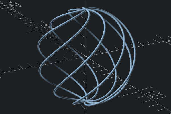
This and some other examples are loosely based on this tutorial.
You can, of course, write your Go code, compile it, run it, and then load the result in OpenSCAD by hand, but that would be cumbersome. All this machinery can be easily integrated with Emacs or other editors and executed using convenient keyboard shortcuts. The GhostSCAD repo provides an example.
The Good
Let's now discuss the advantages of putting up with this additional complexity.
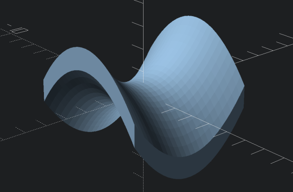
First of all, we're now using a general-purpose programming language. It means that we can solve the first issue discussed in the introduction and have a function grapher that can be used like this when dealing with functions in (x, y) domain:
1func main() {
2  f := func(x, y float64) float64 {
3    return (math.Pow(y, 2) / math.Pow(2, 2)) - (math.Pow(x, 2) / math.Pow(2, 2))
4  }
5  sys.RenderOne(shapes.NewGraph(f, Vec2{-3, 3}, Vec2{-3, 3}, Vec2{0.25, 0.25}).Build())
6}
Or like this when dealing with parametrized functions returning 3D points:
 1func bezierSurface(ctrlPoints [][]Vec3, rangeX Vec2, rangeY Vec2) func(float64, float64) Vec3 {
 2  return func(tx, ty float64) Vec3 {
 3    ptsY := []Vec3{}
 4    for _, pts := range ctrlPoints {
 5      ptsY = append(ptsY, BezierCurve3D(tx, pts))
 6    }
 7    return BezierCurve3D(ty, ptsY)
 8  }
 9}
10
11func main() {
12  ctrlPoints := [][]Vec3{
13    {{0, 0, 20}, {60, 0, -35}, {90, 0, 60}, {200, 0, 5}},
14    {{0, 50, 30}, {100, 60, -25}, {120, 50, 120}, {200, 50, 5}},
15    {{0, 100, 0}, {60, 120, 35}, {90, 100, 60}, {200, 100, 45}},
16    {{0, 150, 0}, {60, 150, -35}, {90, 180, 60}, {200, 150, 45}},
17  }
18  rangeX := Vec2{0, 200}
19  rangeY := Vec2{0, 150}
20  f := bezierSurface(ctrlPoints, rangeX, rangeY)
21  sys.RenderOne(shapes.NewGraphT(f, 0.02).Build())
22}
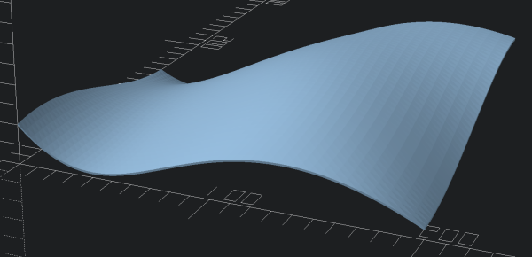
Note that the BezierCurve3D is a library function from the MathGL
library used by GhostSCAD for geometry primitives, so you don't need to
implement it yourself.
Since the program's abstract syntax and geometry trees are separate, you have programmatic access to the geometry nodes. You can use it to solve the remaining two issues described in the introduction without leaking any of the custom module's internals.
For example, in my TV Table Rack project, I have a drawer base module that defines a basic frame for all the drawers:
1type DrawerBase struct {
2  Primitive Primitive
3  Cfg       Config
4
5  Corners []Vec2
6
7  BaseScrew *Anchor
8}
It exposes the corner coordinates computed by the Build method according to
the configuration parameters. Specialized Drawer models may use these
coordinates to create attachments for specific boards.
Another property exposed by this module is the base screw anchor. Anchors allow
you to put complex modules together without knowing anything about their
internals, reference frames, or dimensions. The idea is that you would place an
anchor node in your module's geometry tree where you have done all the necessary
frame transformations and expose it to the outside world. Anchors implement the
Primitive interface, so you can use them just like any other node. They only
render a comment in the resulting OpenSCAD source. Look at lines 12 and 15:
 1o.BaseAttachment = NewAnchor()
 2o.RightConnector = NewAnchor()
 3
 4o.Primitive =
 5  NewDifference(
 6    NewCube(Vec3{o.Cfg.BaseWidth, o.Cfg.Depth, o.Cfg.BaseHeight / 2}),
 7    NewTranslation(
 8      Vec3{0, -pinHoleOffset, 0},
 9      NewCylinder(3*o.Cfg.BaseHeight, o.Cfg.PinRadius+0.1),
10      NewTranslation(
11        Vec3{o.Cfg.BaseWidth / 2, -o.Cfg.BaseWidth / 2, attachmentZOffset},
12        o.BaseAttachment),
13      NewTranslation(
14        Vec3{0, 0, rightConnectorZOffset},
15        o.RightConnector,
16      )))
Calling the Transform method of an anchor traverses the geometry tree from the
anchor up to the root. It creates and returns a Transform node taking its
children from the origin frame of reference to the anchor's frame of reference.
GhostSCAD implements functions such as Align, AlignOrigin, AilignHere that
use anchors to make putting things together trivial:
 1baseB := basesBottom[i]
 2
 3// Attach the columns
 4col := NewColumn(cfg)
 5col.Build()
 6transform := utils.Align(baseB.FrontColumn, col.BaseBottom)
 7rack.Add(transform.Add(col.Primitive))
 8col = NewColumn(cfg)
 9col.Build()
10transform = utils.Align(baseB.BackColumn, col.BaseBottom)
11rack.Add(transform.Add(col.Primitive))
Or like this. Look at lines 17 and 22:
 1lc := NewLeftConnector(o.Cfg, o.Type)
 2rc := NewRightConnector(o.Cfg, o.Type)
 3lc.Build()
 4rc.Build()
 5
 6o.Primitive =
 7  NewList(
 8    NewTranslation(
 9      Vec3{0, -offsetY, 0},
10
11      // Front block
12      NewCube(Vec3{width, o.Cfg.BaseWidth, o.Cfg.BaseHeight}),
13
14      // Right connector
15      NewTranslation(
16        Vec3{width / 2, -o.Cfg.BaseWidth / 2, rightConnectorZOffset},
17        utils.AlignHere(rc.BaseAttachment).Add(rc.Primitive)),
18
19      // Left connector
20      NewTranslation(
21        Vec3{-width / 2, -o.Cfg.BaseWidth / 2, 0},
22        utils.AlignHere(lc.BaseAttachment).Add(lc.Primitive))))
Furthermore, in addition to compiling the whole model to an OpenSCAD source, you
can choose to compile only specific parts of the geometry tree. GhostSCAD
enables that with the RenderMultiple function. It comes in handy when 3D
printing stuff.
 1sys.RenderMultiple([]sys.Shape{
 2  {"blind-right", rBlindBottom.Primitive, sys.None},
 3  {"column", col.Primitive, sys.None},
 4  {"base-power-bottom", basesBottom[0].Primitive, sys.None},
 5  {"base-power-top", basesTop[0].Primitive, sys.None},
 6  {"drawer-power", pd.Primitive, sys.None},
 7  {"drawer-router", rd.Primitive, sys.None},
 8  {"drawer-disk-t5", dd[1].Primitive, sys.None},
 9  {"drawer-disk-t7", dd[0].Primitive, sys.None},
10  {"rack", rack, sys.Default | sys.SkipInBulk},
11})
Finally, it's possible to use the full power of Go, Go's tooling, and Go's libraries. Here's a list of advantages that immediately comes to mind and is by no means exhaustive:
- editor integration - my Emacs setup makes editing Go very convenient
go fmt- you never have to care about source formatting again; there is only one proper way to do it- Go's packaging system - need a library, just
go getit go doc- easily generate documentation for your modules- rich logging - GhostSCAD uses
logrusand allows you to control log verbosity and target via command line; this comes handy when debugging or trying to understand modules - custom command-line options via the builtin
optspackage so that you can parametrize modules without editing the source
Some people may consider using a general-purpose programming language a disadvantage for security reasons. When downloading third-party OpenSCAD modules from the Internet, you usually don't have to worry about messing up your system. Whereas in the case of Go, you need to implement active mitigations and thoroughly review the code you use. I think this is not a high price to pay.
The Bad
Go does not implement operator overloading, so doing math beyond basic floating-point and integer operations is not exactly the most convenient thing in the world. This is why I just use floating-point and not the GMP arithmetics. It may result in precision problems, but I have not encountered them in practice yet.
The OpenSCAD flow control constructs are not used at all. All the computations run in Go, and the generated OpenSCAD sources only contain the final geometry primitives. On the one hand, this should make things faster because Go is a compiled language with better performance characteristics. On the other hand, it often results in large files that OpenSCAD needs to parse and load, which takes time. Doing things this way also tends to mess up with OpenSCAD's geometry cache, which makes things even slower.
GhostSCAD lacks any optimizers for the geometry tree it generates. This may be
problematic, especially for transformations derived from anchors that are never
collated. It could be fixed by using affine transforms and the mulmatrix
primitive. I have not bothered with that for the moment, though, because just
gathering the transforms while traversing the tree seemed easier.
The compilation and code generation times are not noticeable in practice.
The Ugly
Go does not support default parameters in the way OpenSCAD uses them.
Fortunately, it makes code generation relatively easy, so I used it to
generate setters and other convenient methods. Take the implementation of
Cylinder:
 1type Cylinder struct {
 2  ParentImpl
 3  H        float64
 4  RTop     float64
 5  RBottom  float64   "optional"
 6  Center   bool      "optional"
 7  Circular *Circular "forward:SetFa,SetFs,SetFn"
 8  prefix   string    "prefix"
 9}
10
11func NewCylinder(h, r float64) *Cylinder {
12  return &Cylinder{
13    H:        h,
14    RTop:     r,
15    RBottom:  r,
16    Center:   true,
17    Circular: &Circular{},
18  }
19}
20
21func (o *Cylinder) Render(w *bufio.Writer) {
22  w.WriteString(o.Prefix())
23  w.WriteString(
24    fmt.Sprintf(
25      "cylinder(h=%f, r1=%f, r2=%f, center=%t%s);\n",
26      o.H, o.RBottom, o.RTop, o.Center, o.Circular.String(),
27    ),
28  )
29}
The constructor here takes the height and assumes that both the bottom and top
radii are the same. However, OpenSCAD allows you to set them to different
values. GhostSCAD accomplishes the same by marking the data member corresponding
to the bottom radius optional, which leads to the generation of SetRBottom
method.
Furthermore, a struct called Circular handles the parameters of arc fragments using either local or global settings. I annotate a data member of that type to expose specific setter methods in the parent object.
Lastly, marking a string data member as prefix generates the code handling the modifier characters. The resulting code looks as follows:
 1func (o *Cylinder) SetRBottom(val float64) *Cylinder {
 2  o.RBottom = val
 3  return o
 4}
 5
 6func (o *Cylinder) SetFa(val float64) *Cylinder {
 7  o.Circular.SetFa(val)
 8  return o
 9}
10
11func (o *Custom) Prefix() string {
12  return o.prefix
13}
14
15func (o *Cylinder) Disable() Primitive {
16  o.prefix = "*"
17  return o
18}
It works OK for primitives but necessitates a separate build stage for complex shapes. They can only be constructed after all the optional parameters are set to their final values.
Conclusion
In the end, the whole thing worked. I have a neat enough rack and no mess under the TV table, so I am happy. Despite some pain points, I will continue using GhostSCAD and try to improve upon it. If you have ideas for other improvements, do not hesitate to reach out.