Intro
It's kind of silly, but ever since I first watched this scene in "Attack of the Clones," I wanted to build a drone that can evade being hit by a lightsaber:
To gain the understanding of the ecosystem, I decided to buy parts semi-randomly on Amazon, build something that can just fly, and then iteratively improve on this basic design. People can do astounding things with drones these days. My ultimate goal is to be able to build stuff like that.
The hardware
Here's the list of things I have bought:
- A carbon fiber quadrotor frame. (Amazon)
- Brushless rotors. I cannot find the exact model anymore, but they were similar to the ones in the link. (Amazon)
- Electronic Speed Controllers. (Amazon)
- Clock-wise and counter-clock-wise propellers. You only need two of each kind, but they easily break if you do tuning in a confined space, so it's wise to buy more of them upfront. (Amazon)
- A battery. The one in the link is large enough and still fits inside the frame. I need it inside because I wanted the electronics to be easily accessible on the top - I will likely want to change it quite a bit later. (Amazon)
- A power connection board. You can do without it, but it's quite a lot of connections, so soldering wires together and wrapping the joints in isolation tape is painful and looks ugly. (Amazon)
- An autopilot board. I bought a cheap CC3D because I ultimately want to ditch it and build one myself. (Amazon)
- A Raspberry Pi. I want the drone to fly by itself, so I did not buy any radio controller - it will be the task of a computer to do the steering. I used an RPi model 2 because I had one readily available at home. However, these days model 3 is cheaper, so it's probably a much better idea to buy that one. (Amazon)
- A WiFi dongle. I want this first version to be controllable from a web browser via WiFi. A later version will send some telemetry and receive high-level commands via GSM. (Amazon)
Apart from all that, I used some electronics components to power things up and connect them. I had most of them at home, but I will put some links below nonetheless. You'll likely need these:
- A prototyping board. It's nice to solder things together to something stable so that the components don't fly around attached to loose wires. The one in the following link should do. (Farnell)
- A 5V voltage regulator. You will need one to power the Raspberry Pi up. The documentation of CC3D says that the board puts the unregulated output from the ESCs on the output of its serial ports. This output happens to be at 5V, so I initially used that for powering the Pi. Unfortunately, it needs to draw at least around 600 mA of current to work, so the ESC that powered the Raspberry got extremely hot and the motor it was controlling lagged behind the others. Make sure you buy a regulator with as stable output as possible. Some of the cheap ones will make the Raspberry reboot in the middle of the flight due to voltage oscillations. This, in turn, will make the autopilot think it lost the connection to the radio controller and it will go into failsafe mode. A TO-220-compatible heatsink for that regulator is not a bad idea either. You will also need two capacitors. I used 10 μF and 22 μF. Alternatively, you can get yourself a DC to DC converter, in which case you won't need capacitors or heatsinks, and it should be much easier on the battery. (Farnell) (Farnell) or (Farnell)
- An NPN Transistor and two 10 kΩ resistors for a logic inverter with voltage level adjustment. (Farnell)
- Header pins and jumper cables so that you can connect things nicely. (Amazon, Amazon)
I used some extra components, even though they are not necessary to make things work. I am not exactly sure where this project will take me, so it seemed prudent to plan far ahead.
- A 3.3V voltage regulator. I will likely want to power a 3.3V-based microcontroller to act as an autopilot. It needs an extra 10μF capacitor. (Farnell)
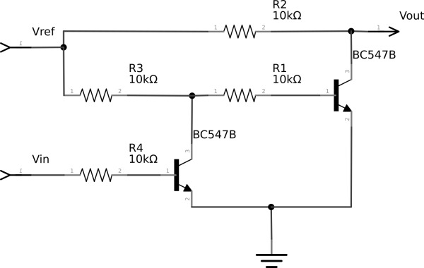
- Four NPN Transistors and eight 10 kΩ resistors for bi-directional voltage level adjusting.
Wiring things up
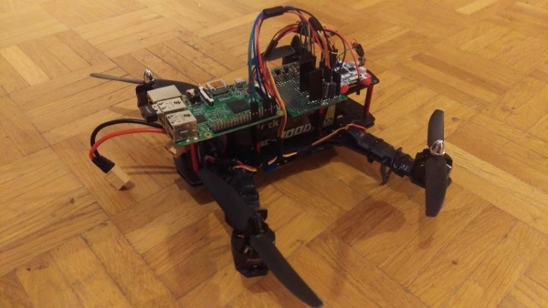
Wiring things up is not hugely complicated. I put the power connection board on the bottom side of the drone together with all the cables powering the ESDs. The ESD control cables and the power for the RaspberryPi go from the bottom to the top in two bunches in the middle of each side of the drone. There are all sorts of electronic-related connections on the top. The battery is inside the drone frame.
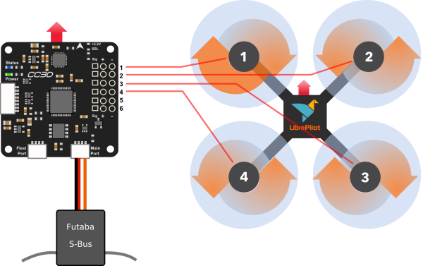
Pretty much the only thing to pay attention to at this stage is making sure that all the rotors are placed in the right positions and that they connect to the ESCs such that they spin in the right directions. Here's a great video on that. The image below was produced by the LibrePilot configuration wizard.
You cannot connect the communication ports of the Raspberry Pi to the CC3D directly because there is a difference in the voltage levels at which the ports operate. The Pi's GPIO works at 3.3V and cannot tolerate 5V. The autopilot should, in principle, work at 3.3V with tolerance to 5V. However, in practice, I found that what only 5V based logic works. This is why I needed to build two voltage level converters out of transistors. I want to use them to send commands and receive telemetry from the FlexiPort of the autopilot.
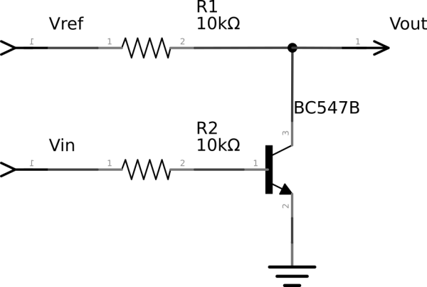
As shown in the rotor topology diagram, the computer controls the autopilot using the S-Bus protocol. This protocol is just transmitting some data over UART with the added quirk of S-Bus being a logical inversion of UART (every 1 in UART is a 0 in S-Bus and vice-versa) plus we need to take care of the voltage level difference in the high states. The best solution here is again to build a circuit that does the inversion. It is a half of the voltage leveling circuit:
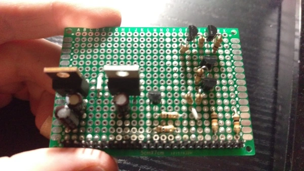
Here's what the resulting board together with the voltage regulators looks like in my case:
Control and Telemetry
A massive bummer of the RaspberryPi for me right now is that it only has one
hardware UART controller. I will need many. At least one more to read telemetry
data from CC3D and, later on, one extra to talk to my WaveShare GSM modem. You
can bitbang UART on GPIOs, and some external
kernel modules out there can do that. The problem is that they rely
on the kernel's hrtimers and are not reliable enough at higher speeds,
especially if the system is under load. I use one for now at a low speed, but I
am working on my own implementation that uses hardware timers to flip the GPIO
states reliably and on time. The CC3D and the Raspberry Pi can talk telemetry
over such simulated serial port using the UAVTalk protocol. The
LibrePilot source code provides python bindings for that.
I used the one hardware UART port that the Pi has for the control link because
it needs to operate at a high and non-standard speed. On RaspberryPis 1 and 2
this port is used as a Linux console output by default, so you will need to
disable that in /boot/config.txt. RaspberryPis 0 and 3 use the hardware UART
to control Bluetooth. This behavior may be disabled by installing the
pi3-disable-bt device tree overlay. All the necessary details are
here. Once you're done with that, you can connect pin 14 of the Pi
to the input of the inverter and the yellow (orange) cable of the CC3D's main
port to its output.
After doing all that, it's a matter of opening the serial port in the right mode
and sending the protocol byte stream down the pipe. S-Bus expects a baud rate of
100000, one even parity bit, and two stop bits. Here's how to open the port in
this mode using Python's pyserial:
import serial

port = serial.Serial('/dev/ttyAMA0', baudrate=100000,
                     parity=serial.PARITY_EVEN,
                     stopbits=serial.STOPBITS_TWO)
I found an excellent description of the S-Bus data frames here. Each frame is 25 bytes long and consists of: a start byte, 16 11-bit channels packed in the next 22 bytes, a byte containing flags and extra binary channels, and, finally, a stop byte. The controller is supposed to send a frame every 7ms, but after reading the code, I found that the LibrePilot firmware is fine as long as it receives a frame at least ten times per second (at least more often than every 102.4ms to be precise). You can see the code of my encoder here.
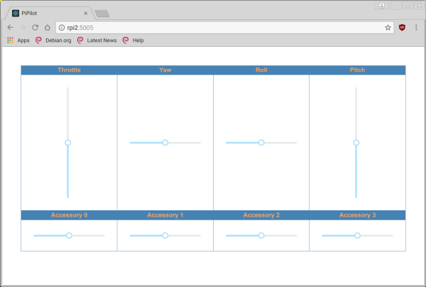
I quickly got tired of putting these numbers in a terminal window, so I wrote a trivial controller that works in a browser and uses a bunch of sliders. The code is on GitHub.
Open/Libre Pilot
There seems to have been some disagreement in the Open/Libre Pilot community,
and the project does not look like it's in a great shape. I needed to make a
bunch trivial changes to the GCS source code to make it compile on my Debian
Testing laptop. Furthermore, the firmware does not build with the cross-compiler
toolchain they supply due to some GCC configuration issues. I managed to build
the firmware using the stock Debian cross-compiler for ARM and modifying the
Makefile to make it not use the -Werror flag. The firmware code has plenty of
unused variables that make the build process fail with this setting turned on.
After building everything, the GCS crashes every other time you try to power
cycle the board. As far as the CC3D boards themselves are concerned, I have two
of them, and only one works in a more or less stable way. The other one does not
load the configuration correctly or hangs every 3 out of 5 boots.
I used the config wizard at the beginning but found it confusing, so I later decided to do the configuration manually. Here's a list of what I did screen-by-screen:
- Hardware:
- Receiver Port: Disabled+OneShot
- Flexi Port: Telemetry
- Main Port: S.Bus
- USB HID Port: USBTelemetry
- Telemetry Speed: 9600 - faster than that is not reliable with current implementations of software UART for RaspberryPi.
- Vehicle - Multirotor:
- Airframe Type: Quad X
- Assigned the rotors to the appropriate channels
- Input:
- Remote Control Input:
- All channels need to be assigned even though not all of them correspond to any inputs in the pipilot interface. Otherwise, you will get receiver warnings, and the copter won't arm. I figured that out the hard way by reading the firmware code. Here's to the great diagnostics!
- Throttle is Channel 1, Yaw - Channel 2, Roll - Channel 3, Pitch - Channel 4.
- Accessories are Channels 5 to 8.
- You can assign other controls to whatever other channels you like.
- S.Bus transmits 11bits worth of data per channel, so the minimum is at 0 and the maximum is at 2047.
- Flight Mode Settings
- Flight Mode Count: 1
- Stabilized 1: Attitude, Attitude, Axis Lock, CruiseControl - CruiseControl is particularly important. If you set it Manual, the copter will behave crazy.
- Arming Settings:
- Arm airframe using throttle off and: Yaw Left
- Remote Control Input:
- Output:
- Set all Modes to PWMSync
- I calibrated the ESCs following these instructions.
- Attitude:
- You want to level your gyros
- People say that there are two ways to combat the copter drifting while
hovering:
- Increase the amount of low-pass filtering.
- Set the virtual rotation to compensate for the board not being completely flat. See this link.
- Neither of these solutions helped me.
Results
If you think it looks completely underwhelming, then I have to agree with you. The main problem is the drift while hovering. I tried virtual rotation, low-pass filtering, and PID tuning, but no amount of configuration tweaking alleviates the problem. The setup does not have any optical sensors and accelerometers, by definition, don't see drifting at a constant speed. On the other hand, the copter is stationary at the beginning and starts to move after the take-off, so the acceleration is not zero. It might be that the sensors are not sensitive enough to pick it up. That's something that I intend to investigate once I get the telemetry connection working reliably.
Update 11.04.2022: Please note that this post was written in March 2018, so some things may not be up to date anymore. In particular, LibrePilot has seen some commits since then, so the situation may have improved. In the meantime, I joined and left a company that works on commercial flight software, so none of the steps mentioned below was carried out. I intend to revisit this project once my non-compete period lapses.
Next steps
Here's what I plan to do next:
- Get my kernel soft UART module based on hardware timers to work. I have the timer interface finished and tested, but still need to do the byte encoder, the GPIO state changing logic, and the TTY interface.
- Connect the telemetry at higher speed to see if the sensors see the drift.
- If the sensors see the drift, either write a PID controller at the level of pipilot or see why the firmware does not compensate for it.
Medium-term plans include:
- Attach the Crazyflie sensor and the IMUs directly to the Raspberry Pi.
- Hack the CC3D firmware so that the Pi can control the motors directly.
- See if Linux (a non-RTOS) on RPi is reliable enough to control the copter and keep it hovering stably.
Long-term plans:
- Port everything to my FRDM-K64F board to see if things improve if implemented on top of "bare metal."
- Start playing with more complex control and estimation math.
- Add cameras, lidar, and implement some autonomy.
- Perhaps write all the microcontroller code in Rust instead of C.